.jpg)
Create Views
Automatically create 2D views of a manifold.
1. MDTools 970 > Create Views
The Create Views dialog box displays.
.jpg)
2. Click Browse and select the block part model.
3. Click Open.
Note:
· Names of the part models, which open in SOLIDWORKS are listed in the File name drop-down list.
· You can also select the part model from the list.
Position
4. Define the scaling between the views dimensions and part model dimensions.
5. Select the current projection type.
Third Angle projection is selected by default.
6. Specify Base View or reference view.
7. Select placement Style of views.
8. Select the positioning option.
The Auto Position option is selected by default.
The distance between views is automatically calculated.
The views are placed with the center of the front view at the center of
the sheet.
9. Deselect
Auto
Position to specify your own position style.
You can select a placement point.
This is the point at which the center of the Front view is placed on the sheet.
10. Specify the inter-view distance.
Display
11. Select Undercut.
MDTools displays Undercuts as circles in Drawing views.
12. Select Angle Hole Direction.
MDTools displays angle holes with direction in Drawing views.
13. Select Engraving Text.
MDTools displays the Engraving text in drawing views.
14. Select Mark X-Ports.
MDTools marks the X-ports as cross symbol in drawing views.
15. Select Internal Details.
MDTools displays the internal details of each face in drawing views.
16. Select Origin and Axes.
MDTools displays the Origin and Axes of each face in drawing views.
17. Select Face Name.
18. Select Outside view Boundary.
MDTools displays face name outside the view boundary.
19. Enter Text Height for the face name.
20. Select Footprint.
Select the options from drop-down for footprint PAN and envelope display.
21. Enter the text height for the footprint PAN text.
22. Click OK.
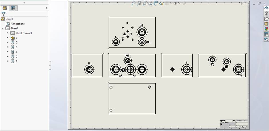
MDTools® automatically creates six views of the selected manifold block, per the options specified in the MDTools Drawing Options dialog box.

MDTools automatically names the views, per the MDTools 2D view naming convention.
- Top view as A
- Front view as B
- Bottom view as C
- Left view as D
- Right view as E
- Back view as F
Note:
· The scale values in the Create View dialog box denote the sheet scale values.
· Refer MDTools Drawing Options for drawing view options.
· The Display Undercut option displays views in wireframe mode for a very short time.