Create Components and Ports List
Insert a cavity table consisting of the component ID, cavity name, and face name in the 2D drawing.
1. MDTools 970 > Components and Ports List
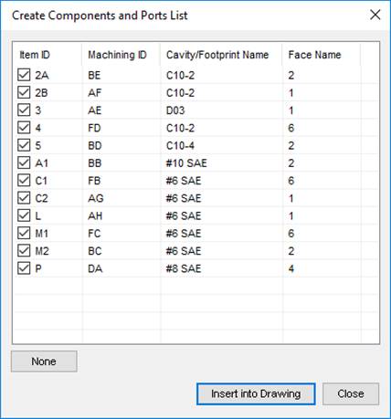
The Create Components and Ports List dialog box displays.

2. Select the cavities to be included in the table.
3. Click Insert into Drawing.
The Select Top Left Corner message displays.
3. Click OK.
4. Select the top left corner to define a rectangular window for the Components and Ports list.
The Select Bottom Right Corner message displays.
5. Click OK.
6. Select the top left corner to define a rectangular window for the Components and Ports list
MDTools®
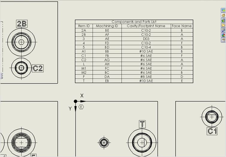
creates the Components and Ports list in the selected window.
When the selected window is insufficient to create the complete Components
and Ports list, the Select Top Left Corner message displays.
7. Repeat the above steps, till the complete Components and Ports list is created in the drawing.

Components and Ports List inserted into a 2D drawing
Note:
Configure Components and Ports List options using MDTools Drawing Options.