Edit Cavity
Change the design specific cavity dimensions inside
SolidWorks.
It also enables you to select a tool (Drill or Spot Face tool) from a tooling
knowledge base. This helps avoid the use of non-standard drills and spot
faces.
1. MDTools 965 > Edit
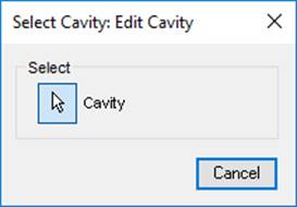
The MDTools® Select Cavity dialog box displays.

2. Select and click the highlighted cavity on the manifold.
When you move the cursor over the cavity, it gets highlighted.
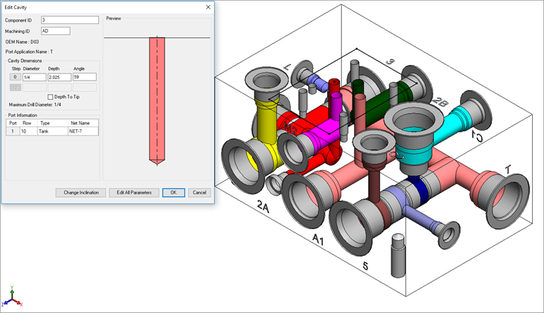
The Edit Cavity dialog box displays.

MDTools displays the cavity preview with the design-specific cavity dimensions.
3. Click Edit All Parameters.
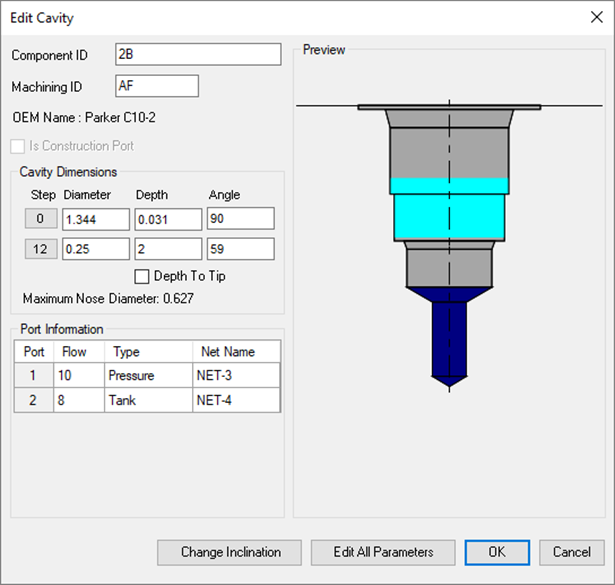
4. View or change all the cavity parameters.
Note:
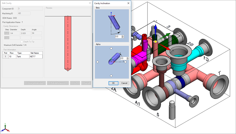
· Click Change Cavity Inclination to change the inclination of a cavity.
· Select the Depth to Tip option to get the drill depth up to the tip.
· The Depth to Tip option is selected, if the Drill Depth Tip option is selected in MDTools Settings.
· You can override the Depth to Tip option locally.
· Port Application Name displays the Footprint type cavity.

Angle Dimension

The Edit Cavity dialog box displays:
· Component ID
· The component ID for the cavity.
· Machining ID
· The
default ID is ‘?’.
This ID is used to identify the hole in the block machining drawing and
the machining chart.
· Spot face and drill dimensions
· Cavity
Insertion angles
(Alpha and Beta)
· Inclination angle is only applicable to drill holes, ports, or cartridge valve cavities.
· Maximum Nose (Drill) Diameter
· This is a reference parameter, therefore not editable during design.
· Port Information
· Enter flow, type, and net name for the cavity.
· When the net name is edited, the color of the cavity is updated according to the color assigned to the net.
· When you click at Net Name Column Net Name pop up occur to select a net from existing nets.