Design Check
Perform connection and wall thickness checks and automatically creates a detailed design report.
The design check report will contain the following
information: -
- Connection checklist
- Quality of connection
- Interference between working area of one cavity and dead area of another
cavity
- Interference between dead area of one cavity and dead area of another
cavity
- Unconnected cavities/ports of cavities
- Wall thickness checklist
- Design Net list
- Connectivity Net list
- Net comparison list
- Broken nets
- Wrong connection inside manifold
- Conformance to Schematic check list
1. MDTools 965 > Design Check
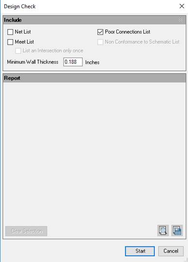
The Design Check dialog box displays.

2. Select the Net list option to include three sections in the report.
· Design Net list
· Connectivity Net list
· Net list comparison
3. Select the Meet List option to include the Meet List section in the report.
‘List an intersection only once’ is part of the Meet List option. If this option is selected, MDTools® removes the repetitive information from the Meet List section.
4. Select Poor Connection to include the Poor Connection section in the report.
5. Select the Conformance to schematic option to view alerts in the report:
· Missing Component and ports.
· Extra Component and ports.
· Wrong Cavities.
· Non-Preferred Construction ports.
· Cavities on Non-Preferred face.
· Wrong Net Name.
· Wrong Port Type.
· Wrong Flow.
6. Enter the minimum wall thickness required.
The default minimum wall thickness is displayed according to the settings.
7. Click on Start to start the Design Check.
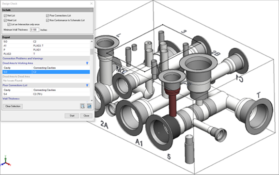
MDTools® checks the wall thickness and connectivity inside the manifold and creates a detailed design check report.
All the cavities in the manifold are grayed out.

8. Select a row, right click on row selection and then select the Show Selected Nets option to highlight issues for Design Net list and Connectivity Net list section.
Similarly compare Net list.
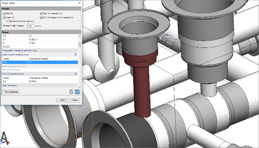
9. Double click on row selection to zoom into the issues.
· MDTools automatically zooms into the problem area for the Wall thickness section.
· MDTools automatically zooms into cavities for the Meet list section.
· MDTools automatically zooms into the Design net section.

10. Click to highlight
the particular section issues.
11. Click to hide
the particular section issues.
12. Click on the Clear Selection option to clear the highlighted issues.
You can view and print the report in a text file by
clicking option.
The Save As dialog box displays.
13. Click to
save the list.
14. Enter an appropriate file name.
CAUTION!
The Undercuts and Slots are not considered in the Design report.
Note:
· Selecting ‘Highlight Design Errors’ in MDTools Options > Misc. enables automatic zoom into the Error section of the design.
· Sections with no issues are grayed out.
· MDTools displays darker shades of gray to show dead area of cavities in order to highlight the cavities.
· MDTools displays actual port net color of cavities in order to highlight the cavities.
· On closing the Design Check dialog, MDTools restores cavity color and cavity center points.