Assembly Interface
Automatically assemble all the components on a manifold. MDTools® automatically creates all the required constraints and assembles the components at the correct location.
Create a new assembly drawing (. sldasm) and place the manifold into the assembly drawing using the Insert Component command in SOLIDWORKS.
1. MDTools 965 > Assembly Interface
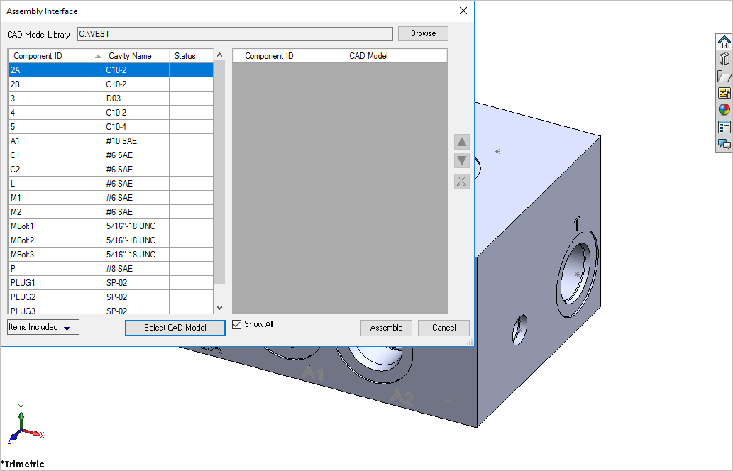
The Assembly Interface dialog box displays.
MDTools displays the Component IDs of all the cavities in the dialog box.
Note:
If there is no manifold placed in the assembly, MDTools shows a message box to check if you want to place a manifold in the assembly.
2. Click Yes.
The Place Component dialog box displays.
3. Click Browse and select the folder containing the part files for the CAD Model Library.
4. Click OK.
5. Click the Select CAD Model button.
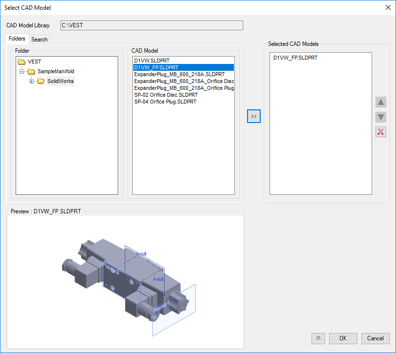
Select CAD Model dialog box
6. Select
a component from the selected CAD
Model list and click  to
include in Selected CAD Models
List
to
include in Selected CAD Models
List
MDTools automatically places the selected component in the assembly drawing.
MDTools displays the Component IDs of all the cavities in the dialog box. Separate components IDs for orifice are merged with the footprint cavities (Parent/child). The status column shows the status of component assembled for that cavity. The Items included option filters the cavity according to the Cavity/Footprint/Orifice type.
7. Click OK.
Note:
The library path is stored in the system registry; therefore, you must have administrative privilege to save changes to the library path.