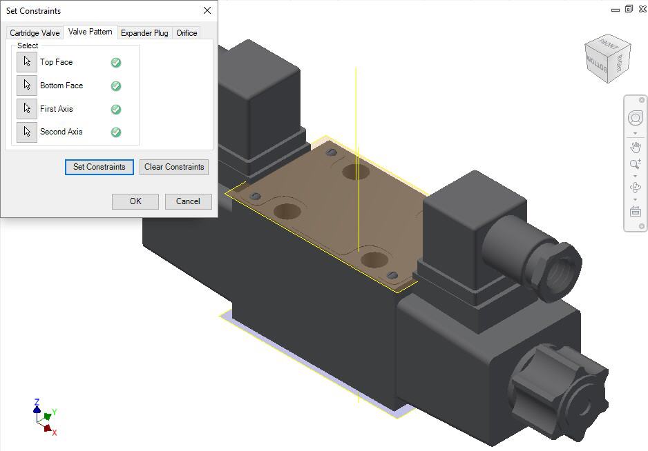
Set assembly constraints for surface mounted valves,
slip-in-cartridge valves, or flanges.
For these components, you need to specify the four parameters: Top Face,
Bottom Face, First Axis, and Second Axis.
1. Create work planes for the top and bottom face.
2. Create
the first axis.
Create a work axis that passes through BH1.
3. Create
the second axis.
Create a work axis that passes through BH2.
4. Select the Top Face button.
5. Select the top face work plane.
6. Select the Bottom Face button.
7. Select the bottom face work plane.
8. Select the First Axis button.
9. Select the axis passing through BH1.
10. Select the Second Axis button.
11. Select the axis passing through BH2.
12. Click Set Constraints to set assembly constraints.
MDTools sets all the assembly constraints. The dialog
box closes.
Now, this part is ready for use with the Assembly Interface.
13. Save the Part Model.
14. Click OK.
Note
BH1 is a bolt hole with the port application name BH1, and BH2 is a bolt hole with the port application name BH2 on the footprint.
MDTools 775 and previous versions used a system that prioritized locating pins for the assembly constraint axes. MDTools 785 will attempt to detect if you are using these old constraints by measuring the distance between axis 1 and 2 and comparing to the distances between LP2/LP1/LP/BH1/BH2