Automatically display the component ID near cavities in the 2D drawing views.
1. MDTools 785 ribbon > Display panel > Component ID
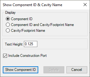
The Show Component ID & Cavity Name dialog box displays.

2. Select the required display option.
Select Component
ID option to display the component ID only.
The Component ID option is selected by default.
Select Component ID & Cavity/Footprint Name option to display the cavity/footprint name with the component ID.
Select Cavity/Footprint Name option to display the cavity/footprint name only.
3. Enter Text Height for component IDs.
4. Select the Include Construction Port option to display the ID for all cavities including construction holes.
5. Click Show Component ID.
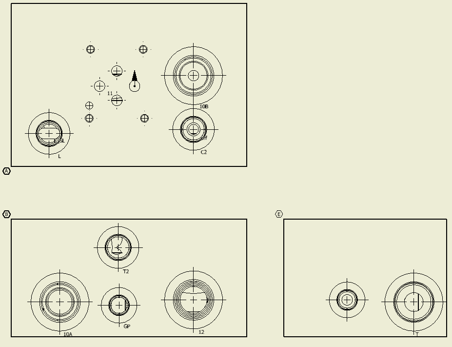
MDTools® displays the component ID near the outermost circle at the bottom of the cavity.
The component ID for all the cavities in a view is created
inside a single sketch.
All component IDs in a view move together when you drag the component ID
text.
To move a single component ID, double click one of the
IDs to open the sketch containing the component IDs.
Drag the cavity component ID to the desired location.
6. Click Delete.
MDTools® deletes all the Component ID’s that exist in the drawing.

Component ID with cavity name in 2D drawing
Note
If 2D views
are created manually, then use the following naming convention for the
manifold views.
Top A
Front B
Bottom C
Left D
Right E
Back F
The Component ID command will not work, if you do not use the view names, per naming conventions.