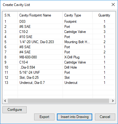
Insert a cavity table consisting of the serial number, cavity/footprint name, cavity type, and quantity in the 2D drawing.
1. MDTools 785 ribbon > Create panel > Cavity List
The Create Cavity List dialog box displays.
2. Click Configure to configure the Cavity List optional fields, column headers and title of the list.
The Configure Cavity List dialog box displays.

3. Select/Deselect the items to be included when the cavity list is inserted. For example: If you want to exclude Mounting Bolt Hole, deselect that option.
4. Select/Deselect the Cavity Type checkbox to display/hide the cavity type.
5. Select/Deselect the Serial Number checkbox to display/hide the serial numbers in the table.
6. Change the Title of the table, if required.
7. Enter Text Height for the Cavity List table.
8. Change the column headers for the customized column headings.
9. Select the delimiter for the text file in the Export Format option.
10. Click OK in the Configure Cavity List dialog box to save the customized settings.
Note
Cavity/Footprint Name and Quantity are always visible in the Cavity List.
11. To export the Cavity list as a text file, click Export.
The delimiter configured is used when creating the text file.
12. Click Insert into Drawing.
13. Click OK.
The Select Top Left Corner message displays.
14. Select the top-left corner to define a rectangular window for the Cavity list.
The Select Bottom Right Corner message displays.
15. Click OK.
16. Select the bottom-right corner to define a rectangular window for the Cavity list.
MDTools® creates the cavity table in the selected window.
If the selected window is insufficient in size to create the complete cavity table, the Select Top Left Corner message displays.
17. Repeat the above steps, till the complete cavity table is created in the drawing.
Note
The active text style in Inventor is used to create the Cavity List table.
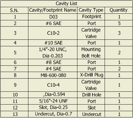
Cavity List inserted in the drawing