1. MDTools 785 ribbon > Block panel > Create (Block)
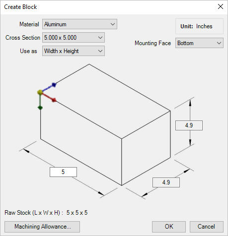
The Create Block dialog box displays.
2. Select the required material.
3. Select Cross Section from the drop-down list and appropriate option from the Use as list.
4. Enter the third dimension for the block, remaining two dimensions are in the Read Only mode.
5. Click the Machining Allowance button.
6. Machining allowances values for Length, Width and Height fields are displayed as per default values from MDTools® Library Manager 2019.
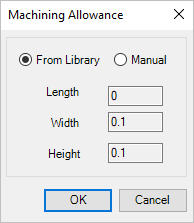
Enter machining allowance values manually, if the Manual option is selected in Machining Allowance dialog.
7. Click OK.
The machining allowance is subtracted from the respective manifold dimensions when drawing the manifold.
The actual block dimensions are displayed on the dialog box. For example, if the manifold width is 4.00 inches and the machining allowance is 0.05 inches, then the manifold width in the part model will be 3.95 inches.
The raw stock dimension is displayed separately on the dialog box.
8. Click OK after the required data is entered.
MDTools automatically creates the block inside Inventor.
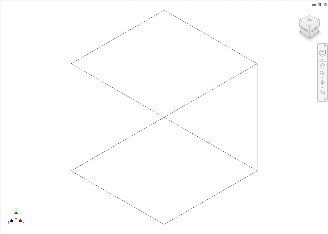
A Block drawn in Inventor
Note
MDTools® uses the following model parameters to define the block dimensions:
Block Length, Block Height, and Block Width.
Do not change these parameter names.
If you change any of these parameter names, the MDTools Modify Block command may give unexpected results.
To create a block manually, which works with MDTools, use the above names for the block model parameters.
If a plate is selected as a Material, then select a thickness from the Cross Section drop-down list and an appropriate option from the Use as drop-down list.
Material cross sections and machining allowances are managed from MDTools Library Manager 2020.