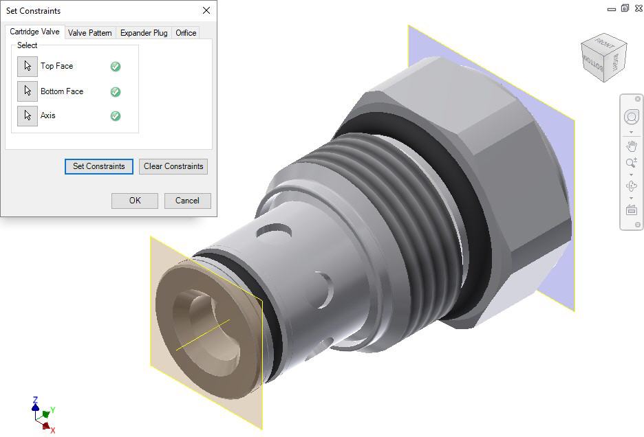

Set the assembly constraints for cartridge valves, port fittings, and plugs. For these components, you need to specify the three parameters, Top Face, Bottom Face, and Axis.
1. Create work planes for top and bottom face.
Note
Work planes should be used to define the top and bottom face. Bottom work plane will mate with the spot face of the cavity during assembly. So, the bottom work plane must be created on the face that needs to mate with the spot face of the cavity.
2. Select the Top Face button.
3. Select the top face work plane.
4. Select the Bottom Face button.
5. Select the bottom face work plane.
6. Select the Axis button.
7. Select an axis passing through the valve body.
8. Click Set Constraints to set assembly constraints.
MDTools®
sets all the assembly constraints and the dialog box closes.
Now, this part is ready for use with the Assembly Interface.
9. Save the model.
Note
Use this option to set the assembly constraints for solenoid coils and lock nut/manual overrides on the screw-in cartridge solenoid valves.