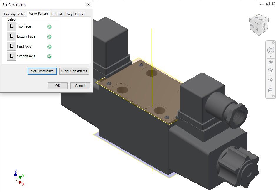
Set assembly constraints for surface mounted valves,
slip-in-cartridge valves, or flanges.
For these components, you need to specify the four parameters: Top Face,
Bottom Face, First Axis, and Second Axis.
1. Create work planes for the top and bottom face.
2. Create
the first axis.
Create a work axis that passes through LP/LP1/BH1.
3. Create
the second axis.
Create a work axis that passes through LP2/BH2.
4. Select the Top Face button.
5. Select the top face work plane.
6. Select the Bottom Face button.
7. Select the bottom face work plane.
8. Select the First Axis button.
9. Select the axis passing through LP/LP1/BH1.
10. Select the Second Axis button.
11. Select the axis passing through LP2/BH2.
12. Click Set Constraints to set assembly constraints.
MDTools sets all the assembly constraints. The dialog
box closes.
Now, this part is ready for use with the Assembly Interface.
13. Save the Part Model.
14. Click OK.
Note
§ Create an axis that passes through the locating pin for valves with one locating pin.
§ Create an axis that passes through the locating pin LP1 for valves with two locating pins.
§ Create an axis that passes through the bolt hole BH1 for valves with no locating pin.
§ Create an axis that passes through the bolt hole BH1 for valves with one locating pin.
§ Create an axis that passes through the locating pin LP2 for valves with two locating pins.
§ Create an axis that passes through the bolt hole BH2 for valves with no locating pin.
LP1 is a locating pinhole with the port application name LP1, and LP2 is a locating pinhole with the port application name LP2 on the footprint.
BH1 is a bolt hole with the port application name BH1, and BH2 is a bolt hole with the port application name BH2 on the footprint.