Check the design for manufacturing and tooling limitations.
This feature enables you to check the manifold for:
- Simple Angle holes
- Compound Angle holes
- Non-standard drills
- Non-standard spot faces
- Drills with slenderness ratio more than the specified value
Single click a row in the report to locate any issue
on the manifold.
Double click a row in the report to zoom into the problem area on manifold.
Select the appropriate Design Check option in MDTools
Settings to locate any issue.
The Highlight Selected Cavities option is the default, selected in MDTools
Settings.
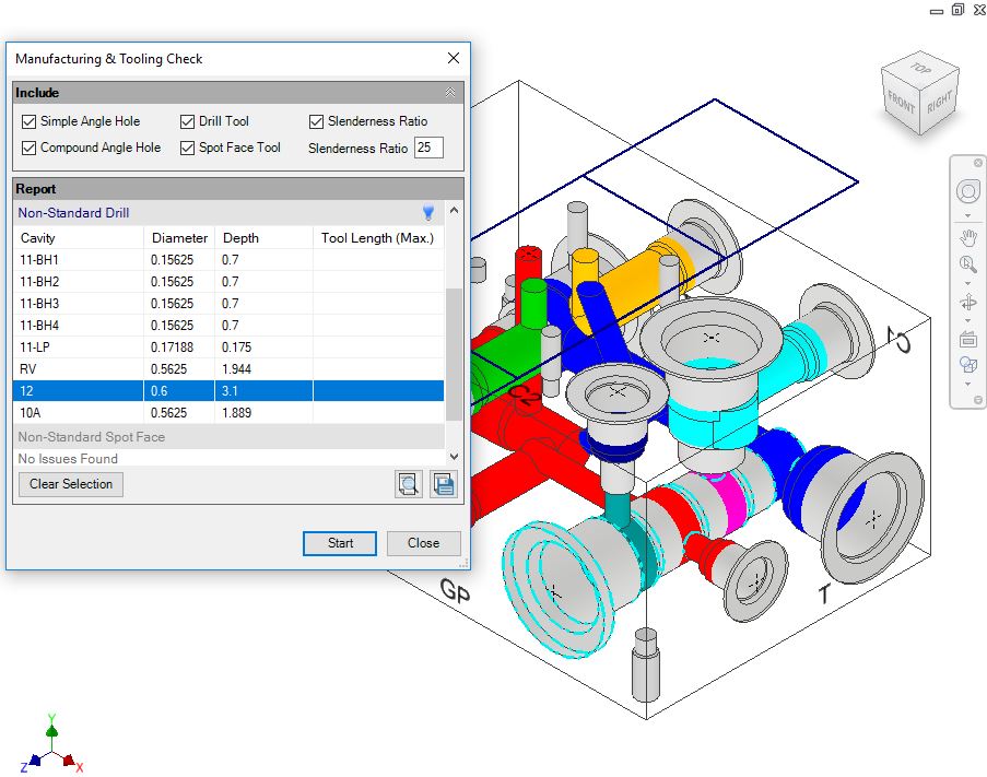
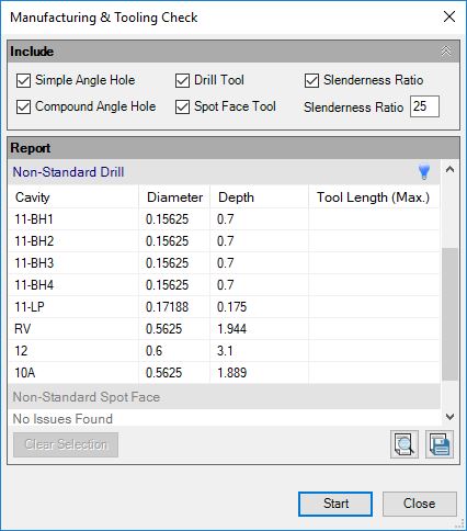
1. MDTools 775 ribbon > Check panel > Manufacturing
The Manufacturing & Tooling Check dialog displays.
2. Select the parameters you want to check.
3. Modify the slenderness ratio.
The default slenderness ratio value is 25.
Manufacturing & Tooling Check dialog box
4. Click Start.
MDTools® checks the manifold design for the selected parameters and lists the cavities deviating from the rule in the dialog box.
5. Select a row.
MDTools highlights the specified issues.
6. Click
 to
highlight specified section issues.
to
highlight specified section issues.
7. Click
 to
hide specified section issues.
to
hide specified section issues.
8. Click Clear Selection to clear the highlighted issues.
9. Click
Save  to
save the list.
to
save the list.
The Save As dialog box displays.
10. Enter an appropriate file name and click Save.
Note
§ If the drill diameter is not available in the Drill Tool database, then MDTools® considers the drill a non-standard drill.
§ If the drill depth is greater than the maximum tool depth in the database, then MDTools considers the drill a non-standard drill.
§ If only Step0 is present in the cavity, then Step0 is considered as the drill, else, Step12 in the cavity is considered a drill.
§ If drill diameter exists in tool library and drill depth is greater than the available drill depth for that diameter in tool library, then Maximum tool length in Non-Standard drill section shows the maximum tool length value.
§ Double click a row in the report to zoom into the problem area/cavity. Step0 of ports and cartridge valve cavities is considered a Spot Face.
§ If the spot face diameter is not available in the Spot Face Tool database, then MDTools considers the spot face as a non-standard spot face.
§ If the spot face depth is greater than the maximum spot face tool depth in the database, then MDTools considers the spot face as a non-standard spot face.
§ If spot face diameter exists in the tool library and the spot face depth is greater than the available spot face depth for that diameter in tool library, then Maximum tool length in Non-Standard spot Face section shows that maximum tool length value.